
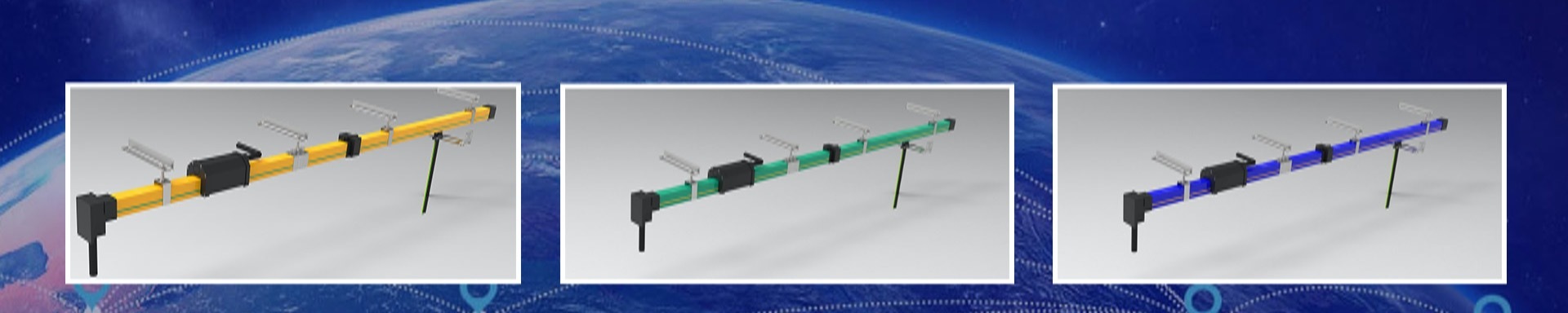


Tubular sliding contact line
SJF multipole conductor system is a safe,economic,widely used reliable power supply devices for mobile electrification applications,is good replacement for cables and traditional steel conductors.It is classified as plastic and aluminum alloy ones as per housing material.Poles from 3 to 16,no oxygen copper as conductor material
- Information

| ltem | Data |
| Voltage Resistant | >25KV/min |
| IP | IP23 |
| Current Resistant | 10 times rated current,1s |
| Max Current | 1.5 times rated current, 30min |
| Insulation Dielectric Strength | Industrial frequency ac 3000v,1min no breakdown and flashover |
| Insulation Resistance | R>10MΩ |
| Pollution Grade | IV(general inductive du st,condensation) |
| Working Voltage | DC:1000V or AC:66V |
| Fire Retardant | Bunsens burner,qualified,good fire-retardant |
| Speed Of Collector | V:120m/min |
| Model | Code | Cross-section mm² | Rated Current A | Resistance Q/km | Impedance Ω/km |  |
| SJFS-3-70/210 | 0810301 | 70 | 210 | 0.257 | 0.292 | |
| SJFS-3-95/270 | 0810302 | 95 | 270 | 0.189 | 0.213 | |
| SJFS-3-120/320 | 0810303 | 120 | 320 | 0.150 | 0.191 | |
| SJFS-3-150/360 | 0810304 | 150 | 360 | 0.120 | 0.165 | |
| SJFS-4-10/50 | 0810401A | 10 | 50 | 1.800 | 1.896 |  |
| SJFS-4-16/80 | 0810402A | 16 | 80 | 1.125 | 1.189 | |
| SJFS-4-25/125 | 0810403A | 25 | 125 | 0.720 | 0.770 | |
| SJFS-4-35/140 | 0810404A | 35 | 140 | 0.514 | 0.558 | |
| SJFS-4-50/170 | 0810405A | 50 | 170 | 0.360 | 0.403 | |
| SJFS-4-70/210 | 0810406A | 70 | 210 | 0.257 | 0.302 | |
| SJF2S-4-10/50 | 0810401B | 10 | 50 | 1.800 | 1.896 |  |
| SJF2S-4-16/80 | 0810402B | 16 | 80 | 1.125 | 1.189 | |
| SJF2S-4-25/125 | 0810403B | 25 | 125 | 0.720 | 0.770 | |
| SJF2S-4-35/140 | 0810404B | 35 | 140 | 0.514 | 0.558 | |
| SJF2S-4-50/170 | 0810405B | 50 | 170 | 0.360 | 0.403 | |
| SJF2S-4-70/210 | 0810406B | 70 | 210 | 0.257 | 0.302 | |
| SJF3S-4-10/50 | 0810401C | 10 | 50 | 1.800 | 1.896 |  |
| SJF3S-4-16/80 | 0810402C | 16 | 80 | 1.125 | 1.189 | |
| SJF3S-4-25/125 | 0810403C | 25 | 125 | 0.720 | 0.770 | |
| SJF2S-5-10/50 | 0810501A | 10 | 50 | 1.800 | 1.896 |  |
| SJF2S-5-16/80 | 0810502A | 16 | 80 | 1.125 | 1.190 | |
| SJF2S-5-25/125 | 0810503A | 25 | 125 | 0.720 | 0.769 | |
| SJF4S-5-10/50F | 0810501B | 10 | 50 | 1.800 | 1.896 |  |
| SJF4S-5-16/80F | 0810502B | 16 | 80 | 1.125 | 1.190 | |
| SJF4S-5-25/125F | 0810503A | 25 | 125 | 0.720 | 0.770 | |
| SJF4S-5-35/140F | 0810504B | 35 | 140 | 0.514 | 0.559 | |
| SJF4S-5-50/170F | 0810505B | 50 | 170 | 0.360 | 0.403 | |
| SJF4S-5-70/210F | 0810506B | 70 | 210 | 0.257 | 0.303 | |
| SJFS-6-10/50 | 0810601A | 10 | 50 | 1.543 | 1.626 |  |
| SJFS-6-16/80 | 0810602A | 16 | 80 | 0.964 | 1.021 | |
| SJFS-7-10/50 | 0810701A | 10 | 50 | 1.800 | 1.897 |  |
| SJFS-7-16/80 | 0810702A | 16 | 80 | 1.125 | 1.191 | |
| SJF2S-6-10/50 | 0810601B | 10 | 50 | 1.542 | 1.626 |  |
| SJF2S-6-16/80 | 0810602B | 16 | 80 | 0.964 | 1.021 | |
| SJF2S-6-25/125 | 0810603B | 25 | 125 | 0.617 | 0.660 | |
| SJF2S-6-35/140 | 0810604B | 35 | 140 | 0.440 | 0.479 | |
| SJF2S-7-10/50 | 0810701B | 10 | 50 | 1.800 | 1.896 |  |
| SJF2S-7-16/80 | 0810702B | 16 | 80 | 1.125 | 1.190 | |
| SJF2S-7-25/125 | 0810703B | 25 | 125 | 0.720 | 0.770 | |
| SJF2S-7-35/140 | 0810704B | 35 | 140 | 0.514 | 0.559 | |
| SJFS-10-10/50 | 0811001 | 10 | 50 | 1.800 | 1.897 |  |
| SJFS-10-16/80 | 0811002 | 16 | 80 | 1.125 | 1.192 | |
| SJFS-10-25/125 | 0811003 | 25 | 125 | 0.720 | 0.771 | |
| SJFS-16-10/50F | 0811601 | 10 | 50 | 1.800 | 1.896 |  |
| SJFS-16-16/80F | 0811602 | 16 | 80 | 1.125 | 1.191 |

| Model | Code | Cross-section mm² | Rated Current A | Resistance Q/km | Impedance Ω/km |  |
| SJFL2-4-10/50 | 0820401A | 10 | 50 | 1.800 | 1.896 | |
| SJFL2-4-16/80 | 0820402A | 16 | 80 | 1.125 | 1.189 | |
| SJFL2-4-25/125 | 0820403A | 25 | 125 | 0.720 | 0.770 | |
| SJFL2-4-35/140 | 0820404A | 35 | 140 | 0.514 | 0.558 | |
| SJFL2-4-50/170 | 0820405A | 50 | 170 | 0.360 | 0.403 | |
| SJFL2-4-70/210 | 0820406A | 70 | 210 | 0.257 | 0.302 | |
| SJFL2-4-95/270 | 0820407A | 95 | 270 | 0.189 | 0.254 | |
| SJFL2-4-120/320 | 0820408A | 120 | 320 | 0.150 | 0.219 | |
| SJFL2-4-150/360 | 0820409A | 150 | 360 | 0.120 | 0.195 | |
| SJFL-5-10/50 | 0820401B | 10 | 50 | 1.800 | 1.897 |  |
| SJFL-5-16/80 | 0820402B | 16 | 80 | 1.125 | 1.205 | |
| SJFL-5-25/125 | 0820403B | 25 | 125 | 0.720 | 0.780 | |
| SJFL-5-35/140 | 0820404B | 35 | 140 | 0.514 | 0.568 | |
| SJFL-5-50/170 | 0820405B | 50 | 170 | 0.360 | 0.410 | |
| SJFL-5-70/210 | 0820406B | 70 | 210 | 0.257 | 0.302 | |
| SJFJ-5-95/270 | 0820407B | 95 | 270 | 0.189 | 0.240 | |
| SJFL-5-10/50 | 0820501 | 10 | 50 | 1.800 | 1.897 |  |
| SJFL-5-16/80 | 0820502 | 16 | 80 | 1.125 | 1.205 | |
| SJFL-5-25/125 | 0820503 | 25 | 125 | 0.720 | 0.780 | |
| SJFL-5-35/140 | 0820504 | 35 | 140 | 0.514 | 0.568 | |
| SJFL-5-50/170 | 0820505 | 50 | 170 | 0.360 | 0.410 | |
| SJFL-5-70/210 | 0820506 | 70 | 210 | 0.257 | 0.302 | |
| SJFJ-5-95/270 | 0820507 | 95 | 270 | 0.189 | 0.240 | |
| SJFL-7-10/50F | 0820701 | 10 | 50 | 1.800 | 1.896 |  |
| SJFL-7-16/80F | 0820702 | 16 | 80 | 1.125 | 1.190 | |
| SJFL-7-25/125F | 0820703 | 25 | 125 | 0.720 | 0.770 | |
| SJEL-7-35/130F | 0820704 | 35 | 140 | 0.514 | 0.559 | |
| SJFL-10-10/50F | 0821001 | 10 | 50 | 1.800 | 1.898 |  |
| SJFL-10-16/80F | 0821002 | 16 | 80 | 1.125 | 1.193 | |
| SJFJ-10-25/125F | 0821003 | 25 | 125 | 0.720 | 0.771 | |
| SJFL-16-10/50 | 0821601 | 10 | 50 | 1.800 | 1.898 |  |
| SJFL-16-16/80 | 0821602 | 16 | 80 | 1.125 | 1.194 |

| Model | Code | Dimension | Weight KG | |||
| L | H | W | M | |||
| GXD-57 | 0810532 | 57 | 70 | 25 | 10 | 0.20 |
| GXD-64 | 0810330 | 64 | 100 | 25 | 10 | 0.24 |
| GXD-70 | 0810533 | 70 | 120 | 20 | 10 | 0.28 |
| GXD-78 | 0810534 | 78 | 128 | 25 | 10 | 0.29 |
| GXD-110 | 0810535 | 110 | 170 | 30 | 12 | 0.35 |

| Model | Code | Dimension | ||
| L | H | W | ||
| GGD-1 | 0810540 | 57 | 70 | 60 |
| GGD-2 | 0810541 | 78 | 110 | 60 |

| Model | Code | Dimension | ||
| L | H | W | ||
| GLJ-1 | 0810545 | 57 | 70 | 63 |
| GLJ-2 | 0810546 | 108 | 104 | 63 |
| GLJ-3 | 0810645 | 123 | 126 | 105 |
| GLJ-4 | 0810646 | 106 | 114 | 110 |

| Model | Code | Dimension | ||
| L | H | W | ||
| GZG-1 | 0810550 | 57 | 70 | 98 |
| GZG-2 | 0810551 | 105 | 116 | 98 |

| Model | Code | Dimension | ||
| L | H | W | ||
| GDG-1 | 0810555 | 57 | 70 | 100 |
| GDG-2 | 0810556 | 110 | 118 | 100 |

| Model | Code | Dimension | ||
| L | H | W | ||
| GDM-1 | 0810556 | 57 | 70 | 62 |
| GDM-2 | 0810656 | 41 | 87 | 62 |
| GDM-3 | 0811656 | 40 | 80 | 70 |
| GDM-4 | 0811657 | 59 | 125 | 105 |

| Model | Code | Dimension | |
| L | H | ||
| GBC-1 | 0810010 | 330 | 90 |
| GBC-2 | 0810020 | 330 | 140 |
| GBC-3 | 0810021 | 330 | 240 |
| GBC-4 | 0810022 | 330 | 190 |

| Model | Code | Dimension | ||
| L | H | W | ||
| GTB-1 | 0810030 | 330 | 110 | 150 |

| Model | Code | Dimension | Weight KG | ||
| L | H | W | |||
| SJS-3-100 | 0810361 | 250 | 170 | 40 | 1.10 |

| Model | Code | Dimension | Weight KG | ||
| L | H | W | |||
| SJS-4-60 | 0810462A | 150 | 160 | 36 | 0.72 |
| SJS-4-150 | 0810463A | 250 | 200 | 35 | 1.56 |

| Model | Code | Dimension | Weight KG | ||
| L | H | W | |||
| SJS-4-60 | 0810462B | 160 | 150 | 35 | 0.6 |
| SJS-4-20 | 0810463B | 115 | 120 | 32 | 0.30 |

| Model | Code | Dimension | Weight KG | ||
| L | H | W | |||
| SJS-7-25 | 0810767 | 130 | 140 | 42 | 0.70 |

| Model | Code | Dimension | Weight KG | ||
| L | H | W | |||
| SJS-7-25 | 0810768 | 130 | 140 | 42 | 0.70 |

| Model | Code | Dimension | Weight KG | ||
| L | H | W | |||
| SJS-10-30 | 0811069 | 220 | 190 | 42 | 1.40 |

| Model | Code | Dimension | Weight KG | ||
| L | H | W | |||
| SJS-16-25 | 0811670 | 220 | 210 | 72 | 2.20 |

| Model | Code | Dimension | Weight KG | |
| L | H | |||
| GZJ-1 | 0811671 | 300 | 40 | 0.60 |

| Model | Code | Dimension | Weight KG | |
| L | H | |||
| GZJ-Ⅱ | 0811672 | 300 | 38 | 0.30 |

| Model | Code | Dimension | Weight KG | |
| L | H | |||
| GLB-1 | 0810081 | 10 | 10 | 0.30 |


Tubular sliding contact lines are mobile power supply devices that encapsulate conductors in insulated pipes. With their unique structural design, they have the following significant advantages in industrial scenarios:
I. Structure and Protective Advantages of Tubular Sliding Contact Lines
1. Fully enclosed insulation design
The conductor (copper or aluminum) is sealed in a high-strength insulating plastic tube (such as PVC, PE) to form a fully enclosed structure, which can effectively prevent dust, rainwater, oil stains, etc. from entering. The protection level can reach IP54 or even higher, making it suitable for harsh environments with high dust, humidity, and corrosive gases (such as mines, chemical workshops, and steel mills).
Insulated pipes also serve a physical protective function, preventing conductors from deforming due to collision or compression, and thus extending their service life.
2. Compact and lightweight in structure
The single-tube sliding contact line integrates the conductor and insulation layer, with an outer diameter typically ranging from 30 to 100mm. It occupies a small space and is suitable for scenarios with limited installation space (such as small cranes and tracks in high-rise warehouses).
Plastic pipes are light in weight, easy to handle and install, which can reduce construction difficulty and labor costs.
3. Multi-pole integrated design
A single pipe can contain 2 to 12 pole conductors (such as three-phase power supply + neutral wire + ground wire), meeting the power supply requirements of multiple circuits. Compared with single-pole sliding contact lines, it saves installation space and has a neater circuit layout.
Ii. Electrical Performance Advantages of Tubular Sliding Contact Lines
It is conductive, stable and safe
The cross-section of the conductor is circular or flat, with a smooth surface. It is in close contact with the collector (slider), and the resistance fluctuation is small during sliding, resulting in high power supply stability. It is suitable for equipment with high requirements for current continuity (such as precision machine tools and automated production lines).
The fully enclosed structure eliminates the risk of exposed conductors, preventing electric shock to personnel or short circuits by foreign objects, and is especially suitable for workshop environments with a high concentration of people.
2. Anti-interference and low energy consumption
The multi-pole conductors are compactly arranged within the same pipe, providing excellent electromagnetic shielding effect and reducing interference with surrounding electronic devices. This makes it suitable for scenarios where automatic control systems are centralized.
The conductor has low resistance and small power loss. When combined with high-quality collectors, it can further reduce contact loss and improve system energy efficiency.
3. Explosion-proof and fireproof characteristics
The insulating materials are mostly flame-retardant (such as flame-retardant PVC), which are not easy to catch fire when exposed to open flames. Moreover, the closed structure can suppress the leakage of electric sparks. If combined with explosion-proof collectors, it can be used in flammable and explosive environments (such as petrochemicals and dangerous goods storage).
Iii. Advantages of Installation and Maintenance of Tubular Sliding Contact Lines
1. Flexible and convenient installation
It supports various installation methods such as straight line, curve and fork. With the matching elbows, tees and other accessories, a complex power supply network can be easily constructed to meet the multi-angle movement requirements of equipment (such as circular production lines and rotating machinery).
It can be installed in a suspended or bracket manner, without the need for pre-embedded tracks. It can be directly fixed on the top of the factory building or beside the equipment, with a short installation period.
2. Low maintenance cost
The closed structure reduces the oxidation and wear of conductors, resulting in a low frequency of collector replacement. Daily maintenance only requires checking whether the pipe connections are loose, without the need for frequent conductor cleaning.
The modular design allows individual pipes to be replaced independently, enabling rapid fault handling and reducing equipment downtime.
3 Scalability and compatibility
The current can be expanded by parallel-connecting multiple sets of tubular sliding contact lines (such as upgrading from 200A to 600A), or by increasing the number of pipes to expand the power supply circuit.
It is compatible with various types of collectors (such as carbon brush type and roller type), and can be flexibly selected according to the operating speed of the equipment (low speed ≤30m/min, medium speed 30~60m/min).
Fourth, the tubular sliding contact line has a wide range of applicable scenarios
· Small and medium-sized lifting equipment: such as electric hoists, single-girder cranes, and suspended conveyors, are especially suitable for indoor workshop environments.
· Automated production lines: such as mobile workbenches in automotive manufacturing and electronic assembly lines, AGV trolley power supply, meeting the power supply requirements of multiple workstations and multiple circuits.
· Light industry and warehousing: Conveyor belt equipment for textile mills and food processing plants, as well as stackers and shuttle vehicles for high-rise warehouses.
· Special environmental scenarios: such as pharmaceutical workshops (with high dust-proof requirements), electroplating production lines (with anti-corrosion requirements), flour processing plants (with explosion-proof requirements).
V. Economic Advantages of Tubular Sliding Contact Lines
1. Low comprehensive cost
Compared with the cable drag chain system, the tubular sliding contact line has a lower initial investment (especially in long-distance scenarios), and does not require frequent cable replacement, significantly reducing long-term maintenance costs.
The price of aluminum conductor tubular sliding contact line is only 1/3 to 1/2 of that of copper conductor, making it suitable for small and medium-sized enterprises that are sensitive to cost.
2. Energy conservation and efficiency improvement
The low-resistance design reduces heat generation and can lower the energy consumption of cooling equipment such as air conditioners, especially showing significant advantages in high-temperature workshops.
Summary
The tubular sliding contact line, with its fully enclosed protection, multi-pole integration, convenient installation and maintenance, and strong environmental adaptability, has become an ideal power supply solution for small and medium-sized mobile devices. When making a selection, based on the current requirements (copper conductors are suitable for high currents, while aluminum conductors are suitable for medium and low currents), environmental grades (such as explosion-proof and anti-corrosion requirements), and the movement speed of the equipment, corresponding specifications of pipes and collectors can be matched to maximize the performance of the system.


